Classification of DC Machines
- DC motors
- DC generators
DC motors
Converts DC power to mechanical power
DC generators
Convert mechanical power to DC electrical power.
Working principle of DC Machines
When electric current flow through a coil within a magnetic field, the interaction of magnetic from electromagnet and that created by current flowing in the coil generates a torque that rotate the DC motors.
Construction of DC Machines
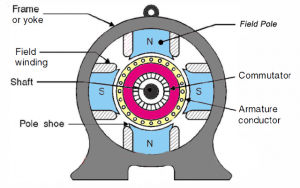
1. Yoke:
It’s also called the frame.
Functions:
1. It provides mechanical support to all Machine assembly.
2. Carries magnetic flux produced by field windings.
( Made of Cast iron or steel )
2. Poles:
Carry field windings
3. Pole shoes :
Functions:
1. Support the field windings
2. Spread out magnetic flux uniform in the air gap
4. Field windings:
Are wound in a way that when energized they become magnetized forming alternate North and South Pole.
(Made up of copper )
5. Armaturecore
It’s the rotor of a DC machine
It has slot to carry field windings.
It’s always laminated to reduce Eddy current losses.
(Made up of thin laminated circular steel)
It’s provided with air holes or air duct for cooling purpose.
6. Armature windings
They are copper conductors placed on armature slots .
They are insulated from each other and from armature core
Methods use are :
1. Lap winding
2. Wave winding
Commutator
In DC generators
Collects the current generated from the armature conductors
In DC motors
It provides current to armature conductors
( Made up of copper )
7. Brushes
Collects and supplies current from commutator
They rest on commutator segments
( Made up of graphite or curbon )
